
Modbus Component
The Modbus protocol is used by many consumer and industrial devices for communication. This component allows components in ESPHome to communicate to those devices via RTU protocol. You can access the coils, discrete inputs, holding registers and input registers from your devices as sensors, switches, selects, numbers or various other ESPHome components and present them to your favorite Home Automation system. You can even write them as binary or float outputs from ESPHome.
NOTE
This page is the starting point for everything Modbus in ESPHome, including hardware setup. See Modbus Controller for polling registers/coils into sensors, Modbus Client for ad-hoc requests, and Modbus Server for serving registers to another device.
The various sub-components implement some of the Modbus functions below (depending on their required functionality):
| Function Code | Description |
|---|---|
| 1 | Read Coil Status |
| 2 | Read Discrete input Status |
| 3 | Read Holding Registers |
| 4 | Read Input Registers |
| 5 | Write Single Coil |
| 6 | Write Single Register |
| 15 | Write Multiple Coils |
| 16 | Write Multiple Registers |
| 23 | Read/Write Multiple Registers |
Function code 23 (0x17, Read/Write Multiple Registers) is available in both roles - as a client action
(modbus_client.read_write_multiple_registers) and as a server handler
(Read/Write Multiple Registers).
Modbus RTU requires a UART Bus to communicate.
# Example configuration entryuart:  ...
modbus:  id: my_client_hub
on_...:  then:    - lambda: id(my_client_hub).queue_pdu(0x07, modbus::helpers::create_write_single_register_pdu(0x05, 0xBEEF));
Configuration variables
Section titled “Configuration variables”-
id (Optional, ID): Manually specify the ID used for code generation.
-
uart_id (Optional, ID): Manually specify the ID of the UART Component if you want to use multiple UART buses.
-
flow_control_pin (Optional, Pin): The pin used to switch flow control. This is useful for RS485 transceivers that do not have automatic flow control switching, like the common MAX485. If your UART supports
flow_control_pin, you should configure this in theuartcomponent, not in themodbuscomponent. -
send_wait_time (Optional, Time): Time in milliseconds before the next ModBUS command is sent when an answer from a previous command has not yet started (i.e. when to timeout and assume no response is coming). Defaults to 2000 ms. Set this value to the maximum time required for the slowest device on the bus to begin responding (time to first byte). If a device starts responding within this time, the next command will be queued and sent after the response is finished, no matter how long the response. This option is only valid when the
roleisclient. -
turnaround_time (Optional, Time): Time in milliseconds before the next ModBUS command is sent after last response is received. This interval allows other devices on the bus time to process messages. Defaults to 600 ms. This value is ideally set to the maximum time required for the slowest device on the bus to process a message and be ready to process another. Note that all devices will receive all messages and will require time to process them even if they don’t need to reply. If devices don’t respond sometimes, it can help to increase this value. This option is only valid when the
roleisclient. -
role (Optional, string): The role of this component,
clientorserver. Defaults toclient.
Performance vs Stability
Section titled “Performance vs Stability”The default settings are aimed to provide high stability (low error rate) for a wide variety of devices. If you are pushing for high throughput performance (i.e. lots of transmissions per minute) you will need to change the defaults.
The most impactful way to increase throughput is to reduce turnaround_time. If all your devices are able to
process messages quickly without missing any, it’s safe to reduce this number, potentially all the way to 0. If you
see devices failing to respond or responding when they shouldn’t (talking over each other) then you need to
increase it.
Reducing send_wait_time generally does not impact performance at all, unless you have devices that are physically
offline. When all devices are responding, send_wait_time does nothing.
Hardware setup
Section titled “Hardware setup”You need an RS485 transceiver module:
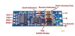
See How is this RS485 module working? on stackexchange for more details.
The transceiver connects to the UART of the MCU. For ESP32, pin 16 to TXD and pin 17 to RXD are the default ones but any other pins can be used as well. 3.3V to VCC and naturally GND to GND.
On the bus side, you need 120 Ohm termination resistors at the ends of the bus cable as per Modbus standard. Some transceivers have this already soldered onboard, while some server devices may have them available via a jumper or a DIP switch.
NOTE
If you are using an ESP8266, serial logging may cause problems reading from UART. For best results, hardware serial is recommended. Software serial may not be able to read all received data if other components spend a lot of time in the loop().
For hardware serial only a limited set of pins can be used. Either tx_pin: GPIO1 and rx_pin: GPIO3 or tx_pin: GPIO15 and rx_pin: GPIO13.
The disadvantage of using the hardware UART is that you can’t use serial logging because the serial logs would be sent to the Modbus device(s) instead, causing errors.
Serial logging can be disabled by setting baud_rate: 0.
See Logger for more details
logger: level: <level> baud_rate: 0See Also
Section titled “See Also”- For polling multiple registers/coils and mapping the response to various kinds of sensors, use Modbus Controller
- For YAML actions & lambdas to send ad-hoc requests to individual devices use Modbus Client
- For serving registers in response to client requests from another device, use Modbus Server
- There are many components which communicate directly via the modbus hub (no controller needed): Growatt Solar, Havells Solar, Kuntze Pool Monitor, PZEMAC, PZEM DC, SDM Meter, Selec Meter
- Modbus Controller platform pages: Sensor, Binary Sensor, Output, Switch, Number, Select, Text Sensor
- Modbus RTU Protocol Description
- All modbus components require a UART Bus
- C++ client component authors should subclass
modbus::ModbusClientDevice - API Reference: modbus.h